First the Basics
I've lost track of the number of times I've been on a customers site and found that they have re-used the old Cat 3 and Cat 4 patch leads simply because they didn't
have any Cat 5 leads at the time. These leads almost never get changed because
it hasn't made any noticeable difference to the operation of the network. Years later
of course, things start to go wrong and the old leads aren't even suspected
because "they've not been a problem in the past".
By all means use old leads on voice systems but never use them on data networks.
It is like throwing a load of rocks into a smooth running stream, the data will
probably still get through at first but when you increase 'the flow', they will start to
impede the throughput.
If the problem only affects one PC, take that PC to the patch
cabinet and plug it directly into the hub. This may seem like an
obvious thing to try but it has to be said as it proves whether the
fault is actually a cabling problem or not. You should use a known good port on the
switch and a known good patch lead, if the machine works then the problem is either the original switch
port, the patch lead, the drop lead or the fixed cabling. From here it is easy to eliminate each part of the
link, but it must be carried out methodically, one component at a time.
Another point worth mentioning is that a patch lead that works fine in a Token Ring network may not
work in an Ethernet network, this is because they use different pins on the RJ45 plug. Token Ring uses
pins 3, 4, 5 & 6 whereas 10BaseT Ethernet uses 1, 2, 3 & 6, so any cable with a fault on pins 1 & 2 will
work for Token Ring but not for Ethernet. Although a Cat 5/5E tester can be very expensive, you can buy
a simple continuity tester for under $100 which will test for shorts, opens and crossed pairs, this will not
prove your cabling is up to standard but they are quick and easy for finding faulty patch leads.
Another thing to watch out for is the wiring configuration, there are actually two different schemes
allowed under the 568A standard. These are called 258A (or T568B), and 258B (or T568A). Pin for pin
they are the same but with the orange and blue pairs swapped over, so as long as you have the same
type of jack at each end, no problem. However, if you have 258A on one end, and 258B on the other
then you have a crossed pair.
they have re-used the old Cat 3 and Cat 4 patch leads simply because they didn't
have any Cat 5 leads at the time. These leads almost never get changed because
it hasn't made any noticeable difference to the operation of the network. Years later
of course, things start to go wrong and the old leads aren't even suspected
because "they've not been a problem in the past".
By all means use old leads on voice systems but never use them on data networks.
It is like throwing a load of rocks into a smooth running stream, the data will
probably still get through at first but when you increase 'the flow', they will start to
impede the throughput.
If the problem only affects one PC, take that PC to the patch
cabinet and plug it directly into the hub. This may seem like an
obvious thing to try but it has to be said as it proves whether the
fault is actually a cabling problem or not. You should use a known good port on the
switch and a known good patch lead, if the machine works then the problem is either the original switch
port, the patch lead, the drop lead or the fixed cabling. From here it is easy to eliminate each part of the
link, but it must be carried out methodically, one component at a time.
Another point worth mentioning is that a patch lead that works fine in a Token Ring network may not
work in an Ethernet network, this is because they use different pins on the RJ45 plug. Token Ring uses
pins 3, 4, 5 & 6 whereas 10BaseT Ethernet uses 1, 2, 3 & 6, so any cable with a fault on pins 1 & 2 will
work for Token Ring but not for Ethernet. Although a Cat 5/5E tester can be very expensive, you can buy
a simple continuity tester for under $100 which will test for shorts, opens and crossed pairs, this will not
prove your cabling is up to standard but they are quick and easy for finding faulty patch leads.
Another thing to watch out for is the wiring configuration, there are actually two different schemes
allowed under the 568A standard. These are called 258A (or T568B), and 258B (or T568A). Pin for pin
they are the same but with the orange and blue pairs swapped over, so as long as you have the same
type of jack at each end, no problem. However, if you have 258A on one end, and 258B on the other
then you have a crossed pair.
Check the time of day!
The time of day may indicate another cause of network problems. If the problem only occurs at a certain
time, it maybe that the network is slowing due to an increase in traffic say at 9:00am or 5:00pm. If, for
instance, the drawing office starts at 9:00am and twenty draughtsmen are all trying to pull large drawing
files from a server which is on the general network, this will impact the rest of the company's business.
Likewise at 5:00pm when they are all saving their work back to the server the sudden increase in traffic
may cause so many collisions that the network to grinds to a halt. A process of elimination is easy to
implement and if this is the cause, it is time to put the drawing office and the CAD server on to its own
switch.
Electrically 'noisy' environments
Another common cause is electromagnetic interference from electric motors and sources of high
frequency radio waves. The more obvious things to look for are cable routes that pass too close to lift
motors, arc and spot welders, heavy plant machinery which use large electric motors, and fluorescent
light fittings. All of these things, if situated close to the data cabling, could induce spikes into the network.
Take a walk around the building and make a note of all possible causes, and then try to eliminate them
one at a time.
What next?
Eliminating possible causes one at a time is the ideal, but sometimes the problem occurs so infrequently
that it is almost impossible to track down, and specialist equipment and engineers have to be employed.
'Network Sniffers' and mains monitors can be hired from companies such as Livingston Hire, and if you
are confident that you can correctly interpret the results, do it yourself. If not, well its the end of the line
and time to call in the specialists.
1.
To summarize, the following considerations should be taken into account:
2.
Low grade patch leads and/or drop leads.
3.
Time of day.
4.
Increase in network traffic from other sources.
5.
Electromagnetic interference.
Ethernet
Most of the points mentioned above should find Ethernet problems, however, there are a couple of
things that should be taken into consideration when dealing with Gigabit Ethernet.
Although Gigabit Ethernet was designed to run on 100MHz cable, problems may arise with older Cat 5
systems. The more stringent Cat 5E standards take into consideration that Gigabit Ethernet uses a four
pair transmission method, but this was not part of the test parameters with Cat 5. If you are trying to run
Gigabit Ethernet over standard Cat 5 cabling, then the whole system should be tested to confirm that it
meets the new Cat 5E standard.
It used to be said that multimode fibre was good for 2km, but recently it has been found that for Gigabit
Ethernet applications the length limit is right down to around 220m over 62.5/125 fibre. The only way to
prove if a fibre is good enough for Gigabit Ethernet is to use a certification tool. These are fairly
expensive test instruments, but you should be able to hire one from a specialist hire company. The
results give a clear 'pass or fail' for different applications, but bear in mind that one dirty connector can
affect the results considerably.
Now some older systems!
Token Ring
Type 1 cable was designed for Token Ring and is a very robust system, however, some of the data
connector termination's I've seen leave a lot to be desired. It is possible to re-terminate these
connectors, so if you have some that are looking decidedly worn or broken, get them fixed. Because of
their large size, data connectors tend to get knocked and bumped and this can be the cause of a lot of
problems. Also remember that Type 1 is a shielded system which has to be grounded properly at the
patch cabinet, ground continuity should also be carried right through to the PC. Failure to ensure proper
grounding can cause a multitude of problems.
The data connector was designed to 'loop back' when unplugged to ensure that if the main ring cabling
is interrupted the network will stay up. If you look into the end of a data connector you will see two gold
strips one behind the other These 'short circuit' the transmit and receive pairs when the connector is
unplugged, and loops the signal back the other way thereby maintaining ring integrity. This very clever
piece of design does have a slight draw back in that a disconnection on the main ring path can go
unnoticed because the data connector is doing its job. This means that if you have a fault on the ring
and it is already working on loop back, you will only know when a second fault occurs. In theory, if your
Token Ring is working perfectly and the ring is complete, you should be able to disconnect the main ring
path anywhere without disrupting the network. If, on the other hand, your Token Ring is already running
on loop back due to a fault that you are not aware of, disconnecting the main ring will effectively split the
network in half.
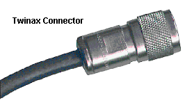
AS400 cabling
AS400e series have three new features which are designed to speed up throughput to
5250 devices, unfortunately some Twinax hardware will not support them.
Split Mode
When operating in Split mode, the AS400 poles its ports two at a time, i.e. 0 & 4, 1 & 5, etc., this only
causes a problem when eight port multiplexors are used as they will be trying to multiplex and de-
multiplex both simultaneous signals. To overcome this, two four port mux's should be used, or the Split
mode feature turned off.
Optimized Mode
In optimized mode no overheads are added to the data frame which under normal conditions works fine,
however some star hubs and mux's need the additional information to work correctly. The solutions are
to either buy new hubs and mux's, or again turn off the Optimized mode feature on the AS400.
Express Mode
This is simply the AS400 running at 2Mbs instead of 1Mbs, and again
some hubs and mux's can't handle this speed. The solution?, same as
above really, buy new hubs or switch off the Express mode feature.
Length limits
The maximum distance for Twinax cable on each port of the Work Station Controller is 1800m, this limit
is reduced to 1458m when running in Express mode. It is also a little known fact that there is a minimum
length limit of 25 feet or about 8m on all types of cable used to transmit 5250 signals. This distance is
the length of the signal itself, and if the cable is less than this, the signal can become corrupted by its
own reflections before it has finished transmitting.
When using IBM Type 1 cabling, the limits are the same as Twinax operation (1800m) but this reduced
to 1312m when running in Express mode.
For UTP installations the distances vary according to whether Twinax is used on part of the installation.
The limits range from a maximum of 364m when only a few metres of Twinax has been used between
the Work Station Controller and the hub, down to a minimum of only 36m where more than 1600m of
Twinax has been used. For further information visit the IBM networking web site.
Where fibre is used between mux's or converters, the maximum limit is 2400m, again
this may be reduced if the AS400 is running in Express mode.
5250 Star hubs
Some active star hubs can introduce delays into the system, if these delays are close to the limits for
5250 operation, it can affect the reliability and performance of the network. Passive star hubs don't
cause delays, so if you are having intermittent problems with a particular line it might be worth trying a
passive star in place of an active one. This is sometimes the case when a line of terminals has been
working perfectly well on the old Twinax but problems start to arise when they are moved to the new
structured cabling.
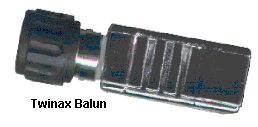
When running 5250 devices over a UTP structured cabling system problems can sometimes be due to
mismatched baluns. Make sure all of the baluns on each line are from the same manufacturer, and that
they are wired for the same pin-out configuration, some star hubs use pins 1 & 2 as the active pins and
some use 4 & 5.
RS232
With RS232, transmit and receive are connected via pins 2 and 3 of the D type plugs with pin 7 (on 25
way) being the ground point. The other pins are used to control the flow of data, usually referred to as
'hard wired handshaking', the pin-out chart below
shows what each pin is used for.
A device can be either a Data Terminal Equipment
(DTE) or a Data Communications Equipment (DCE),
this determines whether pin 2 is transmit and pin 3
receive or vice versa. Usually you will find that
terminals are DTE and printers are DCE and the
ports on the server board will be configured to
communicate with one or the other. This makes a big
difference if you start moving things around and
inadvertently connect terminals or printers into the
wrong ports.


Network Cabling Help - Copyright © 2016 - All rights reserved. - Privacy and Cookie Policy


Fault Finding